Home > Electronics > 3D Printer & Supplies > 3D Printer Module Board
Geekcreit UNO R3 With 4pcs A4988 Driver With CNC Shield V3 Expansion Board For Arduino 3D Printer
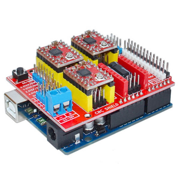
Feature: This expansion board as a driver expansion board, can be used for engraving machines, 3D printers. It is a total of four slots, can drive four A4988 stepper motor. Each road stepper motors only need two IO ports. In other words, six IO ports can be well managed three stepper motors. Very convenient to use. UNO for Arduino module IO port correspondence introduction. Package included: 1 x 3D Printer Expansion Board 1 x UNO R3 board with USB 4 x A4988 driver IO corresponding pin: (For reference only) UNO for Arduino---------------------- expansion board 8 ------------------------ EN ( stepper motor driver enable active low ) 7 ----------------------- Z.DIR (Z -axis direction control ) 6 ----------------------- Y.DIR (Y -axis direction control ) 5 ----------------------- X.DIR (X -axis direction control ) 4 ---------------------- Z.STEP (Z -axis stepper control ) 3 ---------------------- Y.STEP (Y -axis stepper control ) 2 ---------------------- X.STEP (X -axis stepper control ) The following is a simple stepper motor control procedures: # define EN 8 / / stepper motor enable active low # define X_DIR 5 / / X -axis stepper motor direction control # define Y_DIR 6 / / y -axis stepper motor direction control # define Z_DIR 7 / / z axis stepper motor direction control # define X_STP 2 / / x -axis stepper control # define Y_STP 3 / / y -axis stepper control # define Z_STP 4 / / z -axis stepper control / * / / Function : step . function: to control the direction of the stepper motor the number of steps . / / Parameters : dir direction control dirPin corresponding stepper motor DIR pin stepperPin corresponding stepper motor ' step ' pin Step number of step of no return value. * / void step (boolean dir, byte dirPin, byte stepperPin, int steps) { digitalWrite (dirPin, dir); delay (50); for (int i = 0; i digitalWrite (stepperPin, HIGH); delayMicroseconds (800); digitalWrite (stepperPin, LOW); delayMicroseconds (800); } } void setup () {/ / The stepper motor used in the IO pin is set to output pinMode (X_DIR, OUTPUT); pinMode (X_STP, OUTPUT); pinMode (Y_DIR, OUTPUT); pinMode (Y_STP, OUTPUT); pinMode (Z_DIR, OUTPUT); pinMode (Z_STP, OUTPUT); pinMode (EN, OUTPUT); digitalWrite (EN, LOW); } void loop () { step (false, X_DIR, X_STP, 200); / / X axis motor reverse 1 ring, the 200 step is a circle. step (false, Y_DIR, Y_STP, 200); / / y axis motor reverse 1 ring, the 200 step is a circle. step (false, Z_DIR, Z_STP, 200); / / z axis motor reverse 1 ring, the 200 step is a circle. delay (1000); step (true, X_DIR, X_STP, 200); / / X axis motor forward 1 laps, the 200 step is a circle. step (true, Y_DIR, Y_STP, 200); / / y axis motor forward 1 laps, the 200 step is a circle. step (true, Z_DIR, Z_STP, 200); / / z axis motor forward 1 laps, the 200 step is a circle. delay (1000); } Note: When inserting the A4988 module, must be careful not to insert opposite. Stepper motor wiring as follows: 2A, 2B is a group (red, green) 1A, 1B is a group (blue, yellow) if want to change direction, can be change the position of one group for example 2A, 2B mutually exchanged.